810 MIPS Multi-Processor Demonstration Using C Language on PIC®
81 Cooperating 8-bit MCU Cubes Matrix
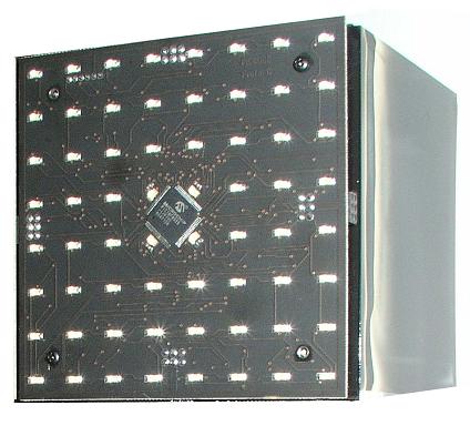
This 9x9 cube matrix is a modular design constructed to demonstrate how PIC18F8525 8-bit MCUs talk via a serial bus. Each individual cube contains one PIC18F8525 that controls each of the 64 LEDs. The well-synchronized multi-processor communication was written in C using the CCS C compiler.
Communication between the microprocessors is done via a one-wire communication, where one cube has an individual communication line to its neighboring cube. Each cube was given a unique address, where the address is based upon its location and distance from the most bottom-left cube. When a cube receives a message, it uses the destination address of the message to determine which direction to route the message on to a neighboring cube. A broadcast message can also be sent out that will be routed to all cubes on the network.
The message instructs a cube to do one of the following:
- Display a specific pattern on the LEDs
- Display pattern on the LEDs from an image in the PIC18F8525 internal memory
- Store a pattern to the PIC18F8525 internal memory
- Manage "bouncy ball" mode
- Manage "game of life" mode
- Set the unique address of the cube
Displaying images is handled by a master device. A master device communicates to the network by instructing all devices to display a pattern; or more efficiently, broadcast a message to the network to display a specific frame from its internal memory.
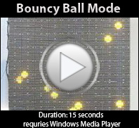
"Bouncy ball" mode is a special effect where the matrix displays via the network a ball bouncing off the 'walls'. In this mode, a broadcast message is sent to all devices telling the cubes where the ball is starting and what the velocity of the bounce will be. While in 'bouncy ball' mode, the timing of all cubes is kept in sync, and each device on the network is responsible for determining its turn to display a ball.


